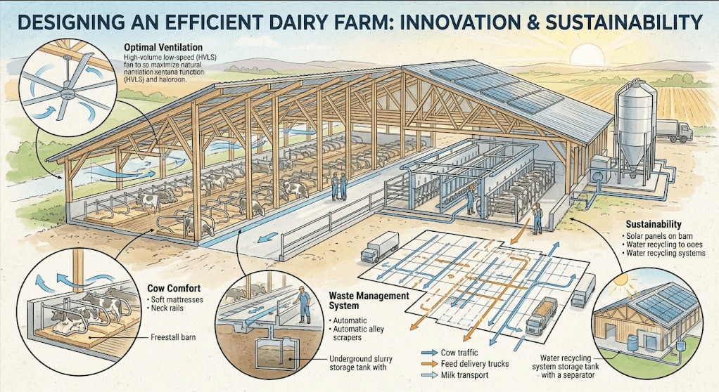
Building or modernizing a dairy facility requires balancing operational workflow with animal welfare. A well-planned dairy farm layout minimizes labor costs, reduces herd stress, improves equipment efficiency, and creates better conditions for milk production. Instead of treating barns, feeding areas, milking facilities, manure systems, and cow traffic as separate projects, modern dairy farms should be designed as one connected production system.
This guide explains the key dimensions, ventilation targets, cow comfort requirements, automation systems, and operational flows that should be considered when planning an efficient modern dairy farm.
Core Principles of Dairy Barn Design
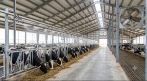
A dairy barn should provide enough space for cows to eat, drink, rest, and move without unnecessary competition. At the same time, workers and machinery need direct access to feeding, cleaning, milking, and maintenance areas.
Key Spatial Specifications and Structural Parameters
| Parameter | Recommended Specification | Direct Operational Impact |
|---|---|---|
| Eave Height | 4.2–5.0 m (14–16 ft) | Helps warm and humid air move upward and supports natural ventilation |
| Roof Slope | 1:3 to 1:4 (approximately 18°–23°) | Supports natural air movement toward the ridge and helps manage condensation |
| Feed Alley Width | 4.5–5.0 m (15–16.5 ft) | Provides operating space for TMR mixers, loaders, and feed pushers |
| Crossover Gangways | Every 15–20 stalls; minimum width around 3.6 m | Improves cow movement between feed, water, resting, and milking areas |
These dimensions should be treated as planning references rather than universal specifications. Final dimensions need to consider herd size, cow body size, local building codes, climate, feeding machinery, manure equipment, and the specific barn configuration.
Understanding the Structural Metrics
Eave Height and Roof Pitch: Higher open sidewalls and an appropriate roof configuration can help warm, moisture-laden air leave naturally ventilated barns. The effectiveness depends on wind exposure, ridge openings, building width, orientation, and surrounding obstructions.
Crossover Gangways: Crossovers allow cows to move between feed alleys, stalls, waterers, and milking routes. Poorly positioned crossovers can create congestion, particularly when water troughs reduce the usable passage width.
The goal is not simply to maximize space. A good dairy farm layout puts space where it improves cow traffic or machinery efficiency.
Optimizing Climate Control: Ventilation and Fans
Heat stress can reduce feed intake, resting behavior, reproductive performance, and milk production. Ventilation should therefore be planned at the same time as the barn structure rather than added after construction.
Environmental Targets Across Barn Zones
Different parts of a barn have different cooling requirements.
| Barn Zone | Planning Air Velocity | Typical Equipment | Main Objective |
|---|---|---|---|
| Freestall Lying Area | 1.5–2.5 m/s | HVLS or circulation/panel fans | Provide effective air movement around resting cows |
| Feed Line / Headlocks | 2.0–3.0 m/s | High-velocity fans + properly designed soakers | Support cooling while cows are feeding |
| Holding Pen | 2.5–3.5 m/s | High-capacity fans + cooling system | Reduce heat load in a high-density waiting area |
Actual fan selection should be based on measured air speed at cow level, barn dimensions, fan performance data, climate, and the complete ventilation design—not fan diameter alone.
Why Air Speed at Cow Level Matters
Installing a powerful fan does not automatically mean cows receive effective cooling.
The important measurement is air movement where the cow is actually standing or lying. Poor fan angle, excessive spacing, structural obstructions, or incorrect mounting height can leave low-airflow zones even when the barn contains many fans.
For this reason, fan planning should consider:
- mounting height,
- fan angle,
- spacing,
- airflow overlap,
- stall and feed-line coverage,
- structural obstructions,
- and measured cow-level air speed.
Feed-Line Cooling
The feed bunk deserves particular attention because heat-stressed cows commonly reduce dry matter intake.
Combining dairy barn fans with properly designed soakers can cool the cow directly. The water wets the animal and subsequent evaporation removes heat, while sufficient air movement accelerates the process.
However, excessive water application can increase bedding moisture, manure volume, water consumption, and slipping risks. Cooling-system design therefore needs to balance cooling performance with water management.
Cow Comfort Equipment and Stall Ergonomics
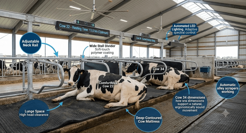
A dairy cow spends a large part of the day resting. Poorly designed stalls can discourage lying, increase standing time, increase manure contamination of the bed, and contribute to injuries or lameness problems.
For that reason, stall dimensions should be matched to the actual cow population rather than copied from another farm.
Example Stall Dimensions for Mature Holstein Cows
[ FRONT / LUNGE ZONE ] <------ RESTING / BEDDING ZONE ------> [ ALLEY ]

+----------------------+--------------------------------------+----------+
| Neck Rail            | Stall Length                         | Grooved  |
|                      |                                      | Concrete |
| Brisket Board        | Stall Width                          | / Rubber |
+----------------------+--------------------------------------+----------+
| Component | Example Planning Range | Why It Matters |
|---|---|---|
| Stall Width | 1.20–1.25 m | Gives mature cows sufficient resting space |
| Single-Row Stall Length | 2.75–2.85 m | Provides body and forward-lunge space |
| Neck Rail Height | 1.20–1.25 m above bed | Helps position cows while maintaining comfortable entry |
| Brisket Board Height | 0.10–0.15 m above bed | Helps position the cow without unnecessarily restricting front-leg movement |
These dimensions are examples for planning a mature Holstein herd. Jersey cows, heifers, dry cows, very large Holsteins, and other groups may require different dimensions.
Head Lunge Clearance
Cows do not simply stand vertically when rising. They shift their weight forward and use their head and neck for momentum.
If the front of a stall is blocked by a wall, rail, or other structure, a cow may struggle to perform this natural movement. That can reduce stall use even when the nominal stall length appears sufficient.
Brisket Board Positioning
The brisket locator helps maintain the cow’s position within the stall. It should guide rather than trap the animal.
Correct positioning helps keep manure toward the alley while still allowing the cow to extend her front legs and lie naturally.
Planning Cow, Feed, Worker, and Machinery Traffic
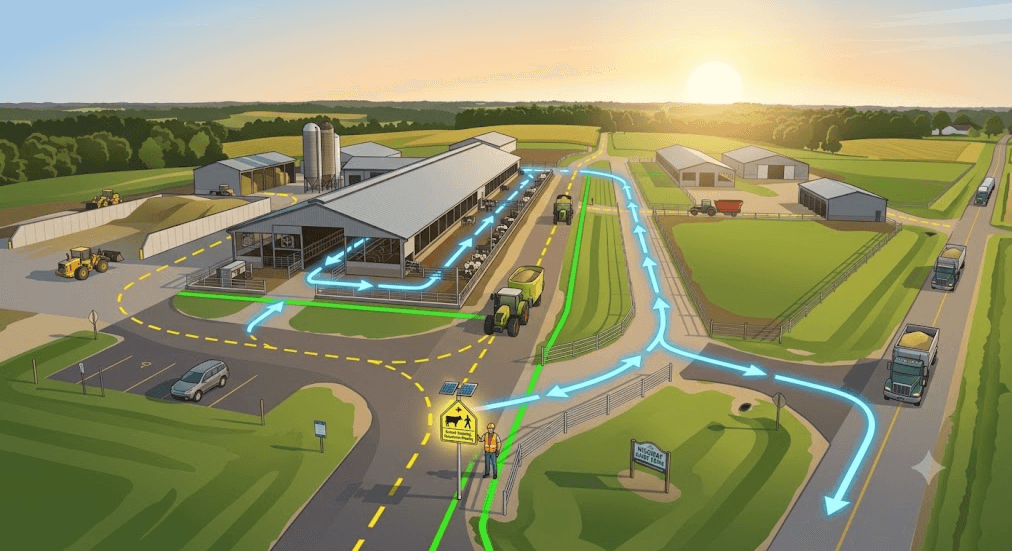
One of the biggest mistakes in dairy design is focusing on individual buildings without examining how everything moves between them.
A practical dairy farm layout should analyze at least six major traffic flows.
| Operational Flow | Preferred Layout Principle | Typical Equipment | Main Benefit |
|---|---|---|---|
| Feed Flow | Short route from storage to mixing and feed alleys | Loader, TMR mixer, feed pusher | Reduces feeding time and fuel consumption |
| Cow Flow | Direct barn-to-parlor routes without dead ends | Gates, lanes, sorting systems | Reduces unnecessary walking and congestion |
| Milk Flow | Short, hygienic connection between milking and milk handling | Milking and cooling equipment | Supports efficient milk handling |
| Manure Flow | Dedicated route toward collection/storage | Scrapers, pumps, manure equipment | Separates dirty and clean operations |
| Worker Flow | Easy access between high-frequency work areas | Service alleys and access points | Reduces unnecessary walking |
| Machinery Flow | Adequate alley width and turning radius | TMR mixers, loaders, tractors | Prevents equipment bottlenecks |
This is where layout design directly affects operating cost.
For example, if a TMR mixer must travel an unnecessary additional 500 meters during every feeding cycle, that distance is repeated every day. Over several years, a poor feed route creates thousands of kilometers of avoidable machinery movement.
Designing the Feeding Area
Feeding is one of the most equipment-intensive daily activities on a modern dairy farm.
A logical feed flow is:
Feed Storage → Ingredient Loading → TMR Mixing → Feed Distribution → Feed Push-Up
Each step should connect directly to the next.
Feed Alley Planning
The feed alley should accommodate the largest machine expected to operate there—not only the equipment currently owned.
| Planning Question | Why It Matters |
|---|---|
| What is the width of the TMR mixer? | Determines minimum machinery clearance |
| What is its turning radius? | Determines intersections and turning areas |
| Will cows be fed from one or both sides? | Changes alley configuration |
| Will an automatic feed pusher be added later? | May require charging/docking space |
| Can a larger mixer be used after herd expansion? | Prevents future barn modifications |
| Can feed be delivered without crossing manure routes? | Improves hygiene and workflow |
A farm planning to expand from 300 to 600 cows should therefore design major feed routes around the future equipment requirement, not simply today’s mixer.
Milking Center and Cow Flow
The milking center can become one of the largest traffic bottlenecks on a dairy farm.
Cows need to move from their home pens to the holding area, through the milking system, and back to the correct group with minimal confusion.
A practical layout should avoid:
- sharp turns,
- narrow bottlenecks,
- slippery intersections,
- unnecessary changes in direction,
- competing two-way cow traffic,
- and machinery crossing primary cow lanes.
Holding Areas
Holding pens deserve particularly careful ventilation and flooring design because cows are concentrated into a relatively small area.
Fans and cooling equipment should therefore be designed specifically for this zone rather than assuming barn ventilation will also cool the holding area adequately.
Automated sorting gates can also be positioned after milking so selected cows can be directed to breeding, treatment, hoof-care, or examination areas without requiring workers to manually locate them later.
Manure Management Should Start With the Layout
Manure management is sometimes treated as equipment selection after the barn has already been designed. This can create expensive problems.
The manure system should instead be planned alongside cow housing.
A typical flow may be:
Cow Alley → Scraper/Flush System → Collection Point → Transfer → Storage/Treatment → Field/Application
| Design Factor | Poor Layout Result | Better Layout Objective |
|---|---|---|
| Long manure route | Higher pumping/scraping requirement | Short direct collection path |
| Manure crossing feed route | Hygiene and traffic conflicts | Separate clean and dirty flows |
| Undersized storage | Expansion limitations | Capacity for planned herd size |
| Difficult equipment access | Slow maintenance | Service access for pumps/scrapers |
| No expansion area | Expensive reconstruction | Reserve space for future capacity |
Designing manure infrastructure for the farm’s expected future herd can be considerably easier than enlarging underground pits, channels, or storage systems later.
Smart Cow Monitoring and Automation Systems
Modern farm design increasingly includes digital infrastructure.
Sensors, RFID identification, automated gates, cameras, environmental monitoring, robotic equipment, and herd-management software all affect the physical layout.
| Technology | Main Data/Function | Layout Requirement | Practical Use |
|---|---|---|---|
| Rumination Collars / Tags | Activity and rumination | Reliable identification/data infrastructure | Detect behavioral changes |
| Ankle Pedometers | Steps, activity, resting | Cow identification system | Support reproduction and comfort monitoring |
| Inline Milk Sensors | Individual milk information | Integration with milking system | Detect production abnormalities |
| RFID Identification | Individual cow identity | Readers at strategic locations | Connect cows with digital records |
| Automatic Sorting Gates | Cow routing | Space after milking/traffic areas | Separate selected cows automatically |
| Environmental Sensors | Temperature/humidity | Multiple barn zones | Control or evaluate ventilation |
| Automatic Feed Pushers | Feed push-up | Clear feed alley + charging area | Reduce repetitive tractor work |
Smart Monitoring Changes Layout Planning
Consider a cow that needs veterinary examination.
In a conventional layout, a worker may need to locate the cow manually, separate her from the group, and move her to a treatment area.
With integrated monitoring and sorting, the workflow can become:
Sensor Alert → Cow Identification → Milking → Automatic Sorting → Treatment Pen
The physical farm layout must support that workflow.
This is why automation should be considered before concrete is poured—even if the farm does not plan to purchase every automated system immediately.
Planning for Different Farm Sizes
The ideal layout also changes with herd size.
| Herd Size | Layout Priority | Typical Equipment Strategy | Main Design Concern |
|---|---|---|---|
| Under 200 cows | Simplicity | Essential mechanization | Avoid overbuilding |
| 200–500 cows | Labor efficiency | TMR feeding, parlor, mechanical manure handling | Prevent growing labor bottlenecks |
| 500–1,000 cows | Process flow | Higher-capacity equipment + monitoring | Coordinate multiple cow groups |
| 1,000–3,000 cows | Throughput | High-capacity feeding, milking and manure systems | Minimize movement and downtime |
| 3,000+ cows | System integration | Automation, specialized equipment and data systems | Reliability, redundancy and logistics |
A small farm should not simply copy a 3,000-cow facility at a smaller scale. Likewise, a 3,000-cow operation cannot efficiently operate as ten disconnected 300-cow farms.
The management system, traffic flow, infrastructure, and equipment strategy must evolve with herd size.
Designing for Future Expansion
A dairy farm may operate for decades, while herd size and technology can change much faster.
For this reason, the initial layout should answer one important question:
What happens if the herd doubles?
Consider future space for:
- additional freestall barns,
- feed storage,
- silage bunkers,
- larger TMR mixers,
- additional cow groups,
- milking expansion,
- manure storage,
- calf and heifer facilities,
- cooling systems,
- renewable energy,
- automated feeding,
- and maintenance facilities.
Future expansion does not mean building everything immediately. It means avoiding construction that blocks logical expansion later.
Key Dairy Farm Layout Planning Checklist
Before finalizing a new facility or major renovation, review the entire operation as one system.
| Planning Area | Key Question | Why It Matters |
|---|---|---|
| Herd Size | How many cows will the farm hold now and in 5–10 years? | Determines infrastructure capacity |
| Barn Design | Is there enough resting, feeding, drinking, and movement space? | Affects cow comfort and traffic |
| Feeding | Can the TMR mixer move efficiently between storage and every group? | Reduces labor, fuel, and feeding time |
| Milking | Can cows reach and leave milking without congestion? | Improves throughput |
| Ventilation | Does effective airflow reach cows throughout the barn? | Helps manage heat and moisture |
| Water | Can cows drink without blocking major traffic routes? | Supports intake and production |
| Manure | Does manure move directly toward collection and storage? | Simplifies waste handling |
| Machinery | Are alleys and turns suitable for current and future equipment? | Prevents machinery bottlenecks |
| Automation | Is the infrastructure ready for sensors, robots, and sorting gates? | Makes future upgrades easier |
| Expansion | Where will the next barn or storage facility be built? | Prevents today’s design from blocking future growth |
Conclusion
An efficient dairy farm layout is much more than the position of barns on a site plan. It determines how cows, workers, feed, milk, manure, machinery, water, air, and information move through the farm every day.
Good design begins with cow comfort and then connects feeding, milking, ventilation, manure management, machinery access, and automation into one coordinated system.
The most important principle is to design around flow.
Feed should move from storage to cows with minimal machinery travel. Cows should reach feed, water, resting areas, and milking facilities without unnecessary congestion. Manure should move toward storage without interfering with clean operations. Workers should spend their time managing cows and equipment rather than walking between poorly positioned facilities.
Finally, design for tomorrow as well as today. Leaving space for a larger TMR mixer, another barn, additional manure capacity, automated sorting, or smart monitoring can cost very little during initial planning but save substantial reconstruction costs later.
A well-designed dairy farm does not simply accommodate more cows—it makes every daily movement easier, safer, and more efficient.