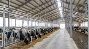
Dairy barn is where an efficient dairy operation begins. A good barn is not simply a roof over cows—it is a working system that connects cow housing, feeding, milking, ventilation, manure removal, staff movement, and future automation.
Learn how dairy farm layout design improves cow comfort, feeding efficiency, ventilation, manure handling, labor flow, and future automation with practical dimensions and planning examples.
For a beginner, barn planning can quickly become confusing. One consultant may focus on stall dimensions, another on ventilation, while an equipment supplier may focus on alley width or machinery access.
The better approach is to design the entire facility as one connected system.
A cow needs enough time and space to rest, eat, drink, walk, and reach the milking area without unnecessary waiting. Workers need safe routes. TMR mixers and manure equipment need enough clearance. Fans need open airflow. Future robots need predictable travel paths.
That is why effective dairy farm layout design should start with cow behavior and daily workflow before construction begins.
1. Start With the Daily Flow, Not the Building Shape
A common mistake is drawing the barn first and trying to fit the dairy operation inside it afterward.
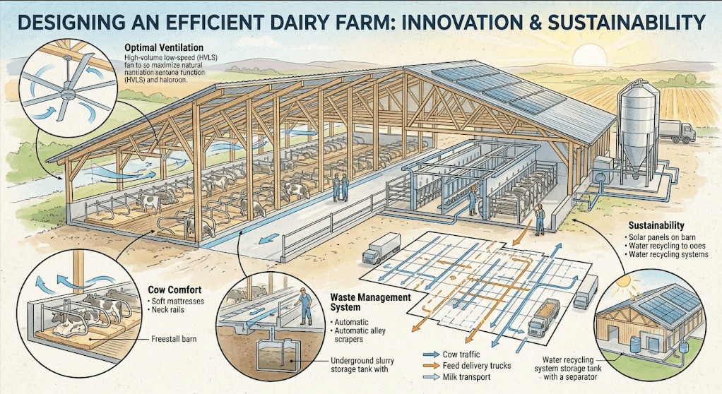
Instead, start by mapping the daily movement of cows, feed, manure, people, and machines.
A basic dairy workflow can be summarized like this:
| Flow | Typical Route |
|---|---|
| Cows | Stall → feed → water → milking → stall |
| Feed | Storage → mixing → feed alley → bunk |
| Manure | Cow alley → scraper/flush → collection → storage |
| Workers | Service area → cows → equipment → milking |
| Milk | Cow → parlor/robot → milk room → storage |
| Equipment | Service entrance → feed/manure alleys → exit |
This simple table is more important than it first appears.
If two major flows constantly cross each other, problems appear later. A feed truck crossing cow traffic can slow feeding. Manure machinery crossing clean milk-room access creates unnecessary hygiene risks. A badly positioned holding pen can increase walking and waiting.
Good dairy farm layout design tries to shorten these routes and reduce unnecessary intersections.
2. Calculate Cow Space Before Choosing Barn Dimensions
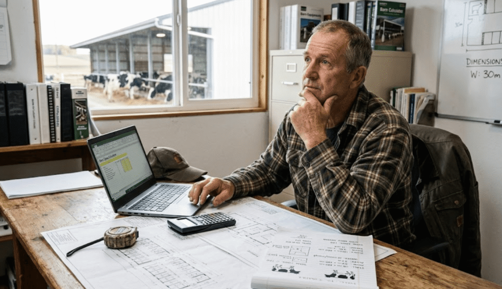
Barn dimensions should come from the cows being housed, not from a standard building width alone.
University of Minnesota Extension recommends approximately 45–48 inches (114–122 cm) of stall width for lactating cows weighing roughly 1,200–1,500 lb, with around 8–8.5 ft (2.44–2.59 m) of stall length when forward lunging is available. (extension.umn.edu)
Penn State provides similar but more detailed guidance. For mature cows weighing 1,300–1,500 lb, suggested freestall width is approximately 45–48 inches, while closed-front stalls may require 102–108 inches of total length because cows need additional forward-lunge space. (extension.psu.edu)
Practical Freestall Planning Range
| Design Item | Planning Range |
|---|---|
| Mature cow stall width | 45–48 in / 114–122 cm |
| Open-front stall length | 90–96 in / 229–244 cm |
| Closed-front stall length | 102–108 in / 259–274 cm |
| Neck rail height | 44–48 in / 112–122 cm |
| Brisket locator height | 4–6 in / 10–15 cm |
| Maximum concrete rear curb | 8 in / 20 cm |
| Desired resting time | 10–14 hr/day |
Sources: Penn State Extension and University of Minnesota Extension. (extension.psu.edu)
For beginners, the important point is simple: larger cows need larger stalls.
Do not copy a stall dimension from another farm without checking cow body size. Holsteins, Jerseys, first-lactation heifers, and mature large-frame cows can require different settings.
Proper stall sizing directly supports cow comfort because cows need enough room to lie down, stretch, rise naturally, and avoid striking rails or partitions. Dairy cows commonly rest about 10–14 hours per day, making the stall one of the most important parts of the barn. (extension.psu.edu)
3. Feed Space Is Part of the Barn Design
Feeding efficiency is not only determined by the TMR mixer.
The barn itself determines whether cows can actually reach the ration.
University of Minnesota Extension gives a planning range of approximately 24–30 inches (61–76 cm) of bunk space per lactating cow, with fresh cows often benefiting from around 30 inches per cow. (extension.umn.edu)
Example: 200-Cow Feeding Pen
Assume:
- 200 lactating cows
- 24 in/cow bunk space
Required usable feed frontage:
200 × 24 in = 4,800 in
4,800 ÷ 12 = 400 ft
So the pen needs approximately 400 ft (122 m) of usable feed-bunk length.
| Herd Group | Typical Planning Bunk Space |
|---|---|
| Lactating cows | 24–30 in/cow |
| Fresh cows | Around 30 in/cow |
| Dry cows | Around 24 in/cow |
| 200 cows at 24 in | 400 ft total |
| 500 cows at 24 in | 1,000 ft total |
Source for per-cow recommendations: University of Minnesota Extension. (extension.umn.edu)
This is why two-row and three-row barns can behave differently even when they contain the same number of stalls.
The important number is not simply “500 cows.” It is how much usable feed frontage each cow receives.
4. Design Feed Alleys Around the Machinery
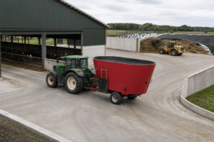
Your dairy barn equipment must be able to enter, operate, turn, and leave without interfering with cows or other machines.
A feed alley may need to accommodate:
- tractor and TMR mixer;
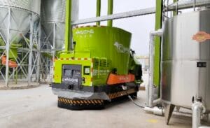
- self-propelled TMR mixer;
- feed distribution wagon;
- automatic feed pusher;
- feeding robot;
- loading or service equipment.
Instead of choosing one universal feed-alley width, measure the actual machine.
A practical engineering check is:
Required alley width = machine width + operating clearance + feed-bunk clearance
For example, if a mixer is 2.6 m wide and the project requires 0.5 m clearance on each side:
2.6 + 0.5 + 0.5 = 3.6 m minimum operational width
This is only a simplified example. Turning areas, doors, mirrors, discharge equipment, safety zones, and local standards may require additional space.
For future robotic feeding, include charging areas and obstacle-free travel routes during the initial dairy farm layout design rather than trying to add them later.
5. Plan a Central Feeding Kitchen for Larger Automated Farms
For medium and large automated dairies, the feeding area may develop into a central feeding kitchen.
Instead of loading every ingredient manually for every batch, ingredients can be stored near a centralized mixing and dispatch area.
A simplified flow is:
Silage & ingredients → weighing → mixing → distribution → feed alley
| Feeding Setup | Main Advantage | Best Fit |
|---|---|---|
| Tractor + TMR wagon | Flexible, familiar | Small–large existing farms |
| Stationary mixer | Centralized mixing | Medium–large farms |
| Central feeding kitchen | Higher automation | Large/new facilities |
| Feeding robot system | Frequent automatic delivery | Automation-focused projects |
The biggest advantage is not simply eliminating a tractor.
Centralization shortens ingredient handling routes and makes automatic weighing, mixing, and group-specific ration delivery easier to integrate.
When evaluating this area, position feed storage as close as practical to the mixing operation. Every unnecessary machine movement becomes repeated labor and energy consumption over thousands of feeding cycles.
6. Ventilation Must Reach the Cow, Not Just the Roof
A barn can look very open and still have poor airflow at cow level.
The ventilation system therefore needs to accomplish two different jobs:
- remove heat, moisture, gases, and stale air;
- create useful air movement around cows.
University of Minnesota Extension notes that hot-weather barns may require approximately 60–90 air exchanges per hour and emphasizes that air velocity at cow level is also critical. (extension.umn.edu)
Penn State notes that tunnel-ventilated dairy housing can require approximately 1,000–1,500 cfm per cow in hot-weather conditions. (extension.psu.edu)
Ventilation Planning Reference
| Item | Hot-Weather Reference |
|---|---|
| Air exchange | 60–90 exchanges/hr |
| Tunnel ventilation | Up to ~1,500 cfm/cow |
| Useful fan airspeed | Often >10 mph locally |
| Fan downward angle example | ~20° |
| Comfortable shade area | ~40 ft²/cow |
Sources: University of Minnesota Extension and Penn State Extension. (extension.umn.edu)
These numbers are design references, not a substitute for a ventilation engineer.
For beginners, think of ventilation like this:
Air exchange replaces dirty hot air. Air velocity cools the cow.
You need both.
Fans should therefore be positioned over high-use areas such as stalls, feed lines, and holding areas rather than simply wherever installation is easiest.
7. Heat Stress Changes the Entire Layout
Cooling should be part of dairy farm layout design, particularly in warm and humid regions.
Water, fans, shade, and holding-pen design all work together.
University of Minnesota reports that a lactating cow producing 80–100 lb of milk/day may drink roughly 25–35 gallons (95–132 L) of water per day in hot weather when daytime highs reach around 90–95°F. (extension.umn.edu)
The same guidance recommends roughly 2 linear inches of accessible water space per cow and trough depth of at least 3 inches. (extension.umn.edu)
| Water Planning Item | Reference |
|---|---|
| Hot-weather intake | 25–35 gal/cow/day |
| Water-space access | 2 linear in/cow |
| Minimum trough depth | 3 in |
| Post-milking intake | Up to 50% of daily intake |
Source: University of Minnesota Extension. (extension.umn.edu)
This explains why water trough placement matters.
If cows return from milking and encounter one small trough in a narrow crossover, dominant cows can block access and traffic can back up.
Water stations should therefore be located where several cows can drink without stopping the main flow of the pen.
8. Design Cow Traffic to Avoid Bottlenecks
Cow movement should feel simple.
A practical route is:
Rest → feed/water → milking → return → rest
Problems appear when cows must make sharp turns, cross machinery routes, wait in narrow passages, or walk excessive distances.
Traffic Planning Checklist
| Area | Design Goal |
|---|---|
| Crossovers | Allow two-way cow movement |
| Return alley | Direct route from milking |
| Holding pen | Minimize unnecessary waiting |
| Water points | Avoid blocking crossover |
| Feed access | Reduce competition |
| Hospital area | Easy staff/equipment access |
| Calving pens | Close to monitoring area |
The goal is not to eliminate every extra meter. It is to remove repeated, unnecessary movement.
Remember that every extra route is multiplied by the number of cows and the number of movements per day.
9. Connect Manure Handling to the Barn From Day One
Manure management should never be treated as an afterthought.
The choice between alley scrapers, robotic cleaners, flush systems, slatted floors, or mechanical collection affects the barn floor, drainage, alley dimensions, storage system, and equipment routes.
| System | Labor Level | Infrastructure Need |
|---|---|---|
| Tractor scraping | High | Low |
| Automatic scraper | Low | Channels/drive units |
| Robotic scraper | Low | Navigable alleys/charging |
| Flush system | Low | Water + drainage |
| Slatted system | Low | Underfloor storage/transfer |
A barn that will eventually use robotic manure cleaners should have smooth navigation paths and accessible charging points.
A flush system, by comparison, requires adequate slopes, water handling, channels, and downstream storage.
This is another reason facility planning and equipment selection should happen together.
10. Separate Special-Needs Cows
Not every cow belongs in the main lactating group.
Good dairy farm layout design should provide dedicated areas for:
- close-up dry cows;
- fresh cows;
- calving cows;
- hospital cows;
- lame cows;
- calves and replacement heifers.
University of Minnesota recommends approximately 50 ft² per cow for early dry cows housed on bedded packs and around 100 ft² per cow for close-up cows. Individual calving pens may be around 140 ft², with common layouts such as 10 × 14 ft or 12 × 12 ft. (extension.umn.edu)
| Special Group | Example Space |
|---|---|
| Early dry cow, bedded pack | 50 ft²/cow |
| Close-up cow, bedded pack | 100 ft²/cow |
| Individual calving pen | ~140 ft² |
| Example calving pen | 10 × 14 ft |
| Alternative pen | 12 × 12 ft |
These areas should also be easy for employees to observe.
A perfect calving pen located far from staff activity may be less useful than a well-designed pen near routine observation routes.
11. Future-Proof the Barn Before Pouring Concrete
The most expensive barn modification is usually the one that requires breaking concrete or moving structural columns.
Before construction, ask what the farm may look like in 5–10 years.
A 500-cow project may eventually become an 800-cow operation.
Future planning might include:
| Today | Future Upgrade |
|---|---|
| Tractor feeding | Feeding robots |
| Manual push-up | Automatic pusher |
| Mechanical scraping | Manure robot |
| Conventional parlor | AMS expansion |
| Basic fans | Automated climate control |
| Local mixing | Central feeding kitchen |
| Manual monitoring | IoT/cow sensors |
Leave electrical capacity, data pathways, expansion space, equipment access, and logical extension points wherever economically practical.
Good planning does not mean purchasing every technology today.
It means avoiding a building that prevents tomorrow’s technology from being installed.
12. A Simple 500-Cow Planning Example
Imagine a new 500-cow freestall dairy.
Using 24 inches of feed space per cow:
500 × 24 in ÷ 12 = 1,000 ft of usable feed frontage
If stalls average 48 inches wide, then 500 stall spaces represent approximately:
500 × 4 ft = 2,000 linear ft of stall frontage
The project must then connect those cows to milking, water, feeding, ventilation, manure handling, and special-needs housing.
| Planning Item | 500-Cow Example |
|---|---|
| Cow capacity | 500 |
| Bunk allowance | 24 in/cow |
| Required bunk frontage | 1,000 ft |
| Example stall width | 48 in |
| Hot-weather water demand at 30 gal/cow | 15,000 gal/day |
| Main systems | Feeding + milking + cooling + manure |
| Future planning horizon | 5–10 years |
The 15,000 gallons/day figure is a planning example using 30 gal/cow under hot-weather conditions; actual consumption varies significantly with milk production, ration moisture, weather, and management. The underlying 25–35 gal/cow hot-weather reference comes from University of Minnesota Extension. (extension.umn.edu)
This example shows why barn planning is a system problem rather than a building problem.
For a beginner, barn planning can quickly become confusing. One consultant may focus on stall dimensions, another on ventilation, while an equipment supplier may focus on alley width or machinery access.
The better approach is to design the entire facility as one connected system.
A cow needs enough time and space to rest, eat, drink, walk, and reach the milking area without unnecessary waiting. Workers need safe routes. TMR mixers and manure equipment need enough clearance. Fans need open airflow. Future robots need predictable travel paths.
That is why effective dairy farm layout design should start with cow behavior and daily workflow before construction begins.
1. Start With the Daily Flow, Not the Building Shape
A common mistake is drawing the barn first and trying to fit the dairy operation inside it afterward.
Instead, start by mapping the daily movement of cows, feed, manure, people, and machines.
A basic dairy workflow can be summarized like this:
| Flow | Typical Route |
|---|---|
| Cows | Stall → feed → water → milking → stall |
| Feed | Storage → mixing → feed alley → bunk |
| Manure | Cow alley → scraper/flush → collection → storage |
| Workers | Service area → cows → equipment → milking |
| Milk | Cow → parlor/robot → milk room → storage |
| Equipment | Service entrance → feed/manure alleys → exit |
This simple table is more important than it first appears.
If two major flows constantly cross each other, problems appear later. A feed truck crossing cow traffic can slow feeding. Manure machinery crossing clean milk-room access creates unnecessary hygiene risks. A badly positioned holding pen can increase walking and waiting.
Good dairy farm layout design tries to shorten these routes and reduce unnecessary intersections.
2. Calculate Cow Space Before Choosing Barn Dimensions
Barn dimensions should come from the cows being housed, not from a standard building width alone.
University of Minnesota Extension recommends approximately 45–48 inches (114–122 cm) of stall width for lactating cows weighing roughly 1,200–1,500 lb, with around 8–8.5 ft (2.44–2.59 m) of stall length when forward lunging is available.
Penn State provides similar but more detailed guidance. For mature cows weighing 1,300–1,500 lb, suggested freestall width is approximately 45–48 inches, while closed-front stalls may require 102–108 inches of total length because cows need additional forward-lunge space.
Practical Freestall Planning Range
| Design Item | Planning Range |
|---|---|
| Mature cow stall width | 45–48 in / 114–122 cm |
| Open-front stall length | 90–96 in / 229–244 cm |
| Closed-front stall length | 102–108 in / 259–274 cm |
| Neck rail height | 44–48 in / 112–122 cm |
| Brisket locator height | 4–6 in / 10–15 cm |
| Maximum concrete rear curb | 8 in / 20 cm |
| Desired resting time | 10–14 hr/day |
Sources: Penn State Extension and University of Minnesota Extension.
For beginners, the important point is simple: larger cows need larger stalls.
Do not copy a stall dimension from another farm without checking cow body size. Holsteins, Jerseys, first-lactation heifers, and mature large-frame cows can require different settings.
Proper stall sizing directly supports cow comfort because cows need enough room to lie down, stretch, rise naturally, and avoid striking rails or partitions. Dairy cows commonly rest about 10–14 hours per day, making the stall one of the most important parts of the barn.
3. Feed Space Is Part of the Barn Design
Feeding efficiency is not only determined by the TMR mixer.
The barn itself determines whether cows can actually reach the ration.
University of Minnesota Extension gives a planning range of approximately 24–30 inches (61–76 cm) of bunk space per lactating cow, with fresh cows often benefiting from around 30 inches per cow.
Example: 200-Cow Feeding Pen
Assume:
- 200 lactating cows
- 24 in/cow bunk space
Required usable feed frontage:
200 × 24 in = 4,800 in
4,800 ÷ 12 = 400 ft
So the pen needs approximately 400 ft (122 m) of usable feed-bunk length.
| Herd Group | Typical Planning Bunk Space |
|---|---|
| Lactating cows | 24–30 in/cow |
| Fresh cows | Around 30 in/cow |
| Dry cows | Around 24 in/cow |
| 200 cows at 24 in | 400 ft total |
| 500 cows at 24 in | 1,000 ft total |
Source for per-cow recommendations: University of Minnesota Extension.
This is why two-row and three-row barns can behave differently even when they contain the same number of stalls.
The important number is not simply “500 cows.” It is how much usable feed frontage each cow receives.
4. Design Feed Alleys Around the Machinery
Your dairy barn equipment must be able to enter, operate, turn, and leave without interfering with cows or other machines.
A feed alley may need to accommodate:
- tractor and TMR mixer;
- self-propelled TMR mixer;
- feed distribution wagon;
- automatic feed pusher;
- feeding robot;
- loading or service equipment.
Instead of choosing one universal feed-alley width, measure the actual machine.
A practical engineering check is:
Required alley width = machine width + operating clearance + feed-bunk clearance
For example, if a mixer is 2.6 m wide and the project requires 0.5 m clearance on each side:
2.6 + 0.5 + 0.5 = 3.6 m minimum operational width
This is only a simplified example. Turning areas, doors, mirrors, discharge equipment, safety zones, and local standards may require additional space.
For future robotic feeding, include charging areas and obstacle-free travel routes during the initial dairy farm layout design rather than trying to add them later.
5. Plan a Central Feeding Kitchen for Larger Automated Farms
For medium and large automated dairies, the feeding area may develop into a central feeding kitchen.
Instead of loading every ingredient manually for every batch, ingredients can be stored near a centralized mixing and dispatch area.
A simplified flow is:
Silage & ingredients → weighing → mixing → distribution → feed alley
| Feeding Setup | Main Advantage | Best Fit |
|---|---|---|
| Tractor + TMR wagon | Flexible, familiar | Small–large existing farms |
| Stationary mixer | Centralized mixing | Medium–large farms |
| Central feeding kitchen | Higher automation | Large/new facilities |
| Feeding robot system | Frequent automatic delivery | Automation-focused projects |
The biggest advantage is not simply eliminating a tractor.
Centralization shortens ingredient handling routes and makes automatic weighing, mixing, and group-specific ration delivery easier to integrate.
When evaluating this area, position feed storage as close as practical to the mixing operation. Every unnecessary machine movement becomes repeated labor and energy consumption over thousands of feeding cycles.
6. Ventilation Must Reach the Cow, Not Just the Roof
A barn can look very open and still have poor airflow at cow level.
The ventilation system therefore needs to accomplish two different jobs:
- remove heat, moisture, gases, and stale air;
- create useful air movement around cows.
University of Minnesota Extension notes that hot-weather barns may require approximately 60–90 air exchanges per hour and emphasizes that air velocity at cow level is also critical.
Penn State notes that tunnel-ventilated dairy housing can require approximately 1,000–1,500 cfm per cow in hot-weather conditions.
Ventilation Planning Reference
| Item | Hot-Weather Reference |
|---|---|
| Air exchange | 60–90 exchanges/hr |
| Tunnel ventilation | Up to ~1,500 cfm/cow |
| Useful fan airspeed | Often >10 mph locally |
| Fan downward angle example | ~20° |
| Comfortable shade area | ~40 ft²/cow |
Sources: University of Minnesota Extension and Penn State Extension.
These numbers are design references, not a substitute for a ventilation engineer.
For beginners, think of ventilation like this:
Air exchange replaces dirty hot air. Air velocity cools the cow.
You need both.
Fans should therefore be positioned over high-use areas such as stalls, feed lines, and holding areas rather than simply wherever installation is easiest.
7. Heat Stress Changes the Entire Layout
Cooling should be part of dairy farm layout design, particularly in warm and humid regions.
Water, fans, shade, and holding-pen design all work together.
University of Minnesota reports that a lactating cow producing 80–100 lb of milk/day may drink roughly 25–35 gallons (95–132 L) of water per day in hot weather when daytime highs reach around 90–95°F.
The same guidance recommends roughly 2 linear inches of accessible water space per cow and trough depth of at least 3 inches.
| Water Planning Item | Reference |
|---|---|
| Hot-weather intake | 25–35 gal/cow/day |
| Water-space access | 2 linear in/cow |
| Minimum trough depth | 3 in |
| Post-milking intake | Up to 50% of daily intake |
Source: University of Minnesota Extension.
This explains why water trough placement matters.
If cows return from milking and encounter one small trough in a narrow crossover, dominant cows can block access and traffic can back up.
Water stations should therefore be located where several cows can drink without stopping the main flow of the pen.
8. Design Cow Traffic to Avoid Bottlenecks
Cow movement should feel simple.
A practical route is:
Rest → feed/water → milking → return → rest
Problems appear when cows must make sharp turns, cross machinery routes, wait in narrow passages, or walk excessive distances.
Traffic Planning Checklist
| Area | Design Goal |
|---|---|
| Crossovers | Allow two-way cow movement |
| Return alley | Direct route from milking |
| Holding pen | Minimize unnecessary waiting |
| Water points | Avoid blocking crossover |
| Feed access | Reduce competition |
| Hospital area | Easy staff/equipment access |
| Calving pens | Close to monitoring area |
The goal is not to eliminate every extra meter. It is to remove repeated, unnecessary movement.
Remember that every extra route is multiplied by the number of cows and the number of movements per day.
9. Connect Manure Handling to the Barn From Day One
Manure management should never be treated as an afterthought.
The choice between alley scrapers, robotic cleaners, flush systems, slatted floors, or mechanical collection affects the barn floor, drainage, alley dimensions, storage system, and equipment routes.
| System | Labor Level | Infrastructure Need |
|---|---|---|
| Tractor scraping | High | Low |
| Automatic scraper | Low | Channels/drive units |
| Robotic scraper | Low | Navigable alleys/charging |
| Flush system | Low | Water + drainage |
| Slatted system | Low | Underfloor storage/transfer |
A barn that will eventually use robotic manure cleaners should have smooth navigation paths and accessible charging points.
A flush system, by comparison, requires adequate slopes, water handling, channels, and downstream storage.
This is another reason facility planning and equipment selection should happen together.
10. Separate Special-Needs Cows
Not every cow belongs in the main lactating group.
Good dairy farm layout design should provide dedicated areas for:
- close-up dry cows;
- fresh cows;
- calving cows;
- hospital cows;
- lame cows;
- calves and replacement heifers.
University of Minnesota recommends approximately 50 ft² per cow for early dry cows housed on bedded packs and around 100 ft² per cow for close-up cows. Individual calving pens may be around 140 ft², with common layouts such as 10 × 14 ft or 12 × 12 ft.
| Special Group | Example Space |
|---|---|
| Early dry cow, bedded pack | 50 ft²/cow |
| Close-up cow, bedded pack | 100 ft²/cow |
| Individual calving pen | ~140 ft² |
| Example calving pen | 10 × 14 ft |
| Alternative pen | 12 × 12 ft |
These areas should also be easy for employees to observe.
A perfect calving pen located far from staff activity may be less useful than a well-designed pen near routine observation routes.
11. Future-Proof the Barn Before Pouring Concrete
The most expensive barn modification is usually the one that requires breaking concrete or moving structural columns.
Before construction, ask what the farm may look like in 5–10 years.
A 500-cow project may eventually become an 800-cow operation.
Future planning might include:
| Today | Future Upgrade |
|---|---|
| Tractor feeding | Feeding robots |
| Manual push-up | Automatic pusher |
| Mechanical scraping | Manure robot |
| Conventional parlor | AMS expansion |
| Basic fans | Automated climate control |
| Local mixing | Central feeding kitchen |
| Manual monitoring | IoT/cow sensors |
Leave electrical capacity, data pathways, expansion space, equipment access, and logical extension points wherever economically practical.
Good planning does not mean purchasing every technology today.
It means avoiding a building that prevents tomorrow’s technology from being installed.
12. A Simple 500-Cow Planning Example
Imagine a new 500-cow freestall dairy.
Using 24 inches of feed space per cow:
500 × 24 in ÷ 12 = 1,000 ft of usable feed frontage
If stalls average 48 inches wide, then 500 stall spaces represent approximately:
500 × 4 ft = 2,000 linear ft of stall frontage
The project must then connect those cows to milking, water, feeding, ventilation, manure handling, and special-needs housing.
| Planning Item | 500-Cow Example |
|---|---|
| Cow capacity | 500 |
| Bunk allowance | 24 in/cow |
| Required bunk frontage | 1,000 ft |
| Example stall width | 48 in |
| Hot-weather water demand at 30 gal/cow | 15,000 gal/day |
| Main systems | Feeding + milking + cooling + manure |
| Future planning horizon | 5–10 years |
The 15,000 gallons/day figure is a planning example using 30 gal/cow under hot-weather conditions; actual consumption varies significantly with milk production, ration moisture, weather, and management. The underlying 25–35 gal/cow hot-weather reference comes from University of Minnesota Extension.
This example shows why barn planning is a system problem rather than a building problem.
Conclusion: Design Around Cows, Workflow, and the Future
Successful dairy farm layout design begins with three questions:
Where do the cows need to go?
Where do the machines need to go?
How can both move with the least conflict?
Start with cow resting and feeding requirements. Then establish feed alleys, water access, milking flow, ventilation, manure routes, and equipment access.
Give particular attention to cow comfort, because cows may spend 10–14 hours every day resting.
After the biological requirements are clear, integrate the ventilation system, dairy barn equipment, feeding automation, and manure management.
For larger new projects, consider whether a central feeding kitchen, feed pusher robots, automatic feeding, or robotic manure equipment may become part of the farm’s future.
The best dairy farm layout design is not necessarily the largest or most automated barn. It is the facility where cows, people, feed, milk, manure, air, water, and machinery move efficiently as one system.
And that is much easier—and much cheaper—to achieve on the drawing board than after the concrete has been poured.